
I’ve been seeing some network problems lately, at sites where the problem was designing the VPC and routing mix correctly. Generally, there’s plenty of room to make a mistake, the situation is a bit confusing to most people. So I’m going to try to explain how to separate out routing and Layer 2 (L2) forwarding with VPC’s, so the routing will work correctly. I’m hoping to help by explaining the problem situation you need to avoid as simply as I can, and showing some simple examples, with lots of diagrams. For a simple description of how basic VPC works, see my prior posting, How VPC Works.
Cisco has put out some pretty good slideware on the topic, but there are an awful lot (too many?) diagrams. Either that’s confusing folks, or people just aren’t aware that VPC port channels have some design limitations, you can’t just use them any which way as with normal port channels (or port channels to a VSS’d 6500 pair).
The short version of the problem: routing peering across VPC links is not supported. (Adjacency will be established but forwarding will not work as desired.) The “vpc peer-gateway” command does not fix this, and is intended for another purpose entirely (EMC and NetApp end systems that learn the router MAC address as the source MAC in frames, rather than using ARP and learning the default gateway MAC address).
Let’s start by repeating the basic VPC forwarding rule from the prior blog:
VPC Rule 101
VPC peers are expected to forward a frame received on a member link out any other member link that needs to be used. Only if they cannot do so due to a link failure, is forwarding across the VPC peer link and then out a member link allowed, and even then, the cross-peer-link traffic can only go out the member link that is paired with the member link that is down.
The same rules apply to routed traffic. Since VPC does no spoofing of the two peers being one L3 device, packets can get black-holed.
The Routing with VPC Problem
Here’s the basic situation where we might be thinking of doing VPC and can get into trouble. Note I’ve been using dots for routed SVI’s, just as a graphical way to indicate where the routing hops are. (No connection with the black spot in the novel Treasure Island.)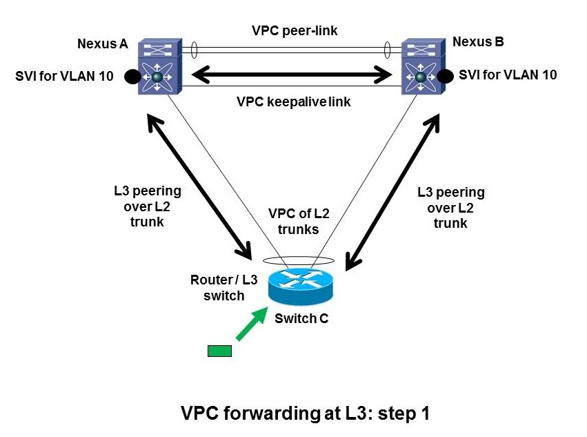
This is where we have a L3-capable switch and we wish to do L2 LACP port-channeling across two Nexus chassis. If the bottom switch is L2-only, no problem. Well, we do have to think about singly-homed servers, orphan (singly-homed) devices, non-VPC VLANs, failure modes, etc., but that is much more straight-forward.
All is fine if you’re operating at Layer 2 only.
Let’s walk through what VPC does with L3 peering over a L2 VPC port-channel. Suppose a packet arrives at the bottom switch C (shown by the green box and arrow in the diagram above or below). The switch has two routing peers. Let’s say the routing logic decides to forward the packet to Nexus A on the top left. The same behavior could happen if it chooses to forward to B. The router C at the bottom has a (VPC) port channel. It has to decide which uplink to forward the packet over to get it to the MAC address of the Nexus A at the top left.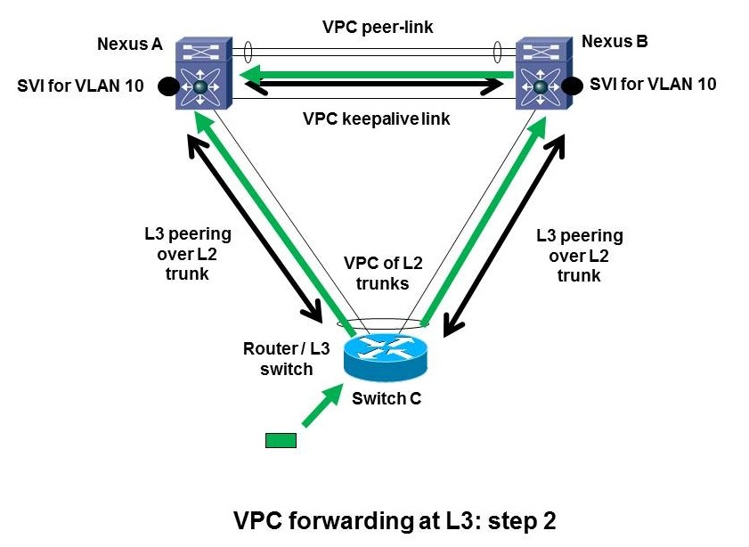
Approximately 50% of the time, based on L2 port channel hashing, the bottom L3 switch C will use the left link to get to Nexus A. That works fine. Nexus A can forward the frame and do what is needed, i.e. forward out another member link.
The other 50% or so of the time, port channel hashing will cause router C to L2 forward the frame up the link to the right, to Nexus B. Since the destination MAC address is not that of Nexus B, Nexus B will L2 forward the frame across the VPC peer link to get it to A. But then the problem arises because of the basic VPC forwarding rule. A is only allowed to forward the frame out a VPC member link if the paired link on Nexus B is down. Forwarding out a non-member link is fine.
So the problem is in-on-member-link, cross-peer-link, out-another-member-link: no go unless paired member link is down. Routing does not alter this behavior.
Yes, if there is only one pair of member links, you cannot have problems, until you add another member link. If you add a 2nd VLAN that is trunked on the same member links, inter-VLAN routing may be a problem. If you just do FHRP routing at the Nexus pair, no, the L2 spoofing handles MAC addresses just fine (using the FRHP MAC so no transit of the peer link is necessary). It’s when your inter-VLAN routing is via an SVI on one of the bottom switches routing to a peer SVI on the Nexus pair that you will probably have problems.
You can have similar problems even if only one of the two Nexus switches is operating at L3, or has a L3 SVI in a VLAN that crosses the VPC trunks to the switch at the bottom. We will see an example of this later.
Conclusion: it is up to us to avoid getting into this situation! That is, VPC is not a no-brainer, if you want to mix it with routing you must design for that.
You can also do this sort of thing with two switches at the bottom of the picture, e.g. pair of N5K to pair of N7K’s. Or even VSS 6500 pair to VPC Nexus pair. See also our Carole Reece’s blog about it, Configuring Back-to-Back vPCs on Cisco Nexus Switches, and the Cisco whitepaper with details. VPC is allowed and works, but we need to design it to operate at L2 only.
Drilling Down on VPC Routing
We are also OK if we use a FHRP with a VPC to get traffic from a VPC’d server to a pair of Nexii, and then route across non-VPC point-to-point links, e.g. into the campus core or WAN. VPC does very well at spoofing L2, and the virtual MACs used with the three FHRP’s allow direct forwarding out VPC member links by VPC peers. Routing to the core uses non-VPC non-member links, so no problem.
The problem in the L3 story above is that the frame is being forwarded at L2 to the real MAC not virtual MAC of A, and B is not allowed to do the routing on behalf of A.
The next diagram shows how this typically bites us. If we’re migrating from 6500’s (bottom) to Nexus (top) and we are inconsistent, we can get in trouble. If our packet hits an SVI, is routed to Nexus B but sent via Nexus A, then Nexus B will not be able to route the frame again out the member link marked with the red X, to get to a L3 SVI on the bottom right switch D.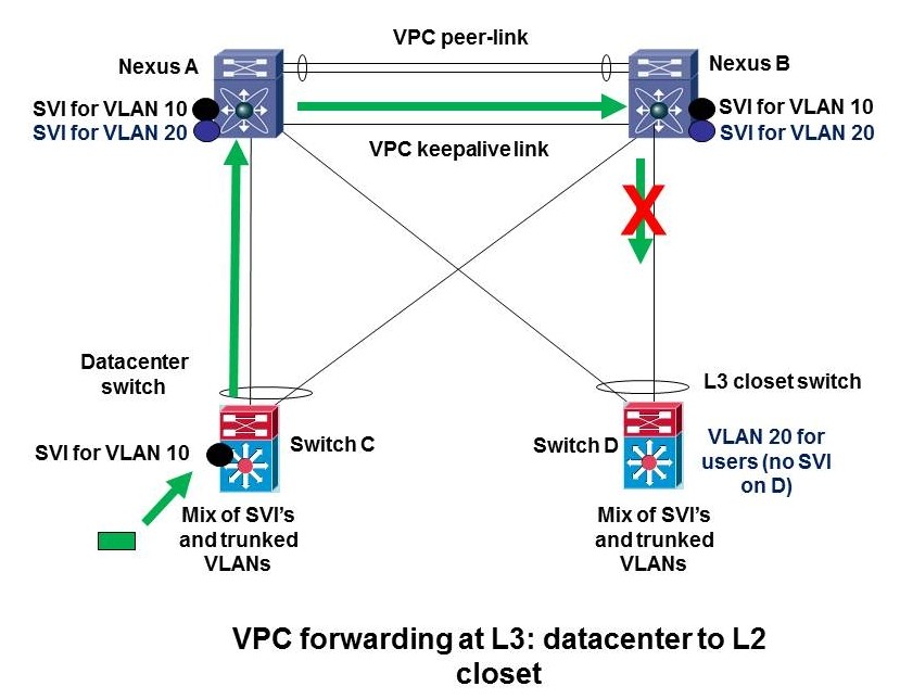
This might happen from datacenter to user closet, if you have L2 to a collapsed core/distribution Nexus pair, with some SVI’s between old 6500 C and new Nexus switches A and B in the datacenter, and closet switches with SVI’s on the same switches as the datacenter SVI’s (switch D in the diagram). It might also happen if you have some VLANs with SVI’s on datacenter access switches like C, and other VLANs on other datacenter access switches like switch D (perhaps even with all SVI’s migrated to live only on the Nexus pair). It can even happen on one switch, where C and D are the same switch, and you’re routing between VLANs via an SVI on C. (Same picture, just a little more cluttered because the green arrow and red X are on the link back to C.)
Summary: Making Routing Work with VPC
Here’s the Cisco-recommended design approach, using my drawing and words. The black links are L2 VPC member links. The red links are additional point-to-point routed links.
The simple design solution is to only allow L2 VLANs with SVI’s at the Nexus level across the VPC member links. If you must have some SVI’s on the bottom switch(es) and some others on the Nexus switches, block those VLANs on the L2 trunks that are VPC members, and route them instead across separate L3 point-to-point links, shown in red in the above diagram. Of course, if you’re routing say VLAN 20, there would be no point to having a routed SVI for VLAN 20 on the bottom switch and on the Nexus switches as well.
The point to point routed interfaces do not belong to VLANs, so they cannot possibly accidentally be trunked over the member links, which are usually trunks.
When you have SVI’s rather than routed interfaces or dot1q subinterfaces, you have to be aware of which VLANs you do and do not allow on the VPC member links. If you have many VLANs that need routing, use dot1q subinterfaces on the routed point-to-point links to prevent “VPC routing accidents”. Or use SVI’s and trunking over the point-to-point non-VPC links, just be very careful to block those VLANs on the VPC trunk member links.
Using VPC to Buy Time to Migrate to L3 Closets
As you will have noticed in my recent blog, Simplicity and Layer 2, I like L3 closets. That generally means your L2 is mostly confined to the datacenter. No L2 problems out in the closets!
Our present discussion is highly relevant if you are migrating from L2 to L3 closets. Several hospitals we are working with have had spanning tree problems (or risk). They wish to reduce their L2 domains size and any risk by moving to L3 closets. One way to tackle this is to drop Nexus switches in at the core or distribution layer (they are sometimes combined layers), and start out running VPC to all the L2 closets. That “stabilizes the patient” to buy time and stability for the cure, L3 closets.
If you whittle away at sprawling VLANs spanning closets, buildings and campuses, you can generally manage to clean up one closet at a time. Iterate for the next year or two. Painful, but much more robust!
Consider a single closet switch that you’re working on. You can get yourself to a situation where the SVI’s are in the distribution layer Nexuses, say, and you have L2 VPC member trunks to the closet switch (now represented by the bottom switch in our above diagrams). When all the VLANs are single-closet-only VLANs, you can then un-VPC the uplinks to that one closet, turn them into point-to-point routed links, put the SVI’s on the closet switch instead, and be done. If you want a slower transition, add separate L3 routed point-to-point links like the above red lines, and control which VLANs are trunked across the VPC member links. All it takes is organization and being clear about where you’re doing L2 and where you’re doing L3 — which I’d say should be part of the design document / planning.
Another Example
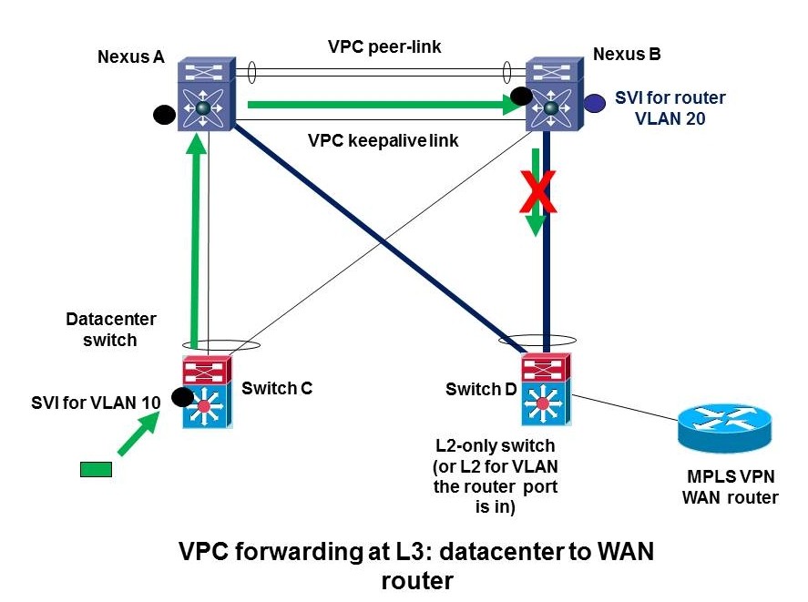
One more real world example shows how it is easy to not see the potential problem. Suppose you have a router, e.g. an MPLS WAN router, and for some reason you have to attach it to a legacy switch at the bottom of the picture, as shown in the following diagram:


Why would you do this? In one case we’ve seen, the vendor router had a FastEthernet port, and the Nexus switch had no 100 mbps capable ports. Another is copper versus fiber ports and locations of the devices in question.
Suppose the uplinks are VPC members, and because of the VPC routing problems, the site is trying to make this work with just a VPC on the right Nexus switch, switch B. In the case in question,; C and D were actually the same switch, but I’m presenting it this way since the diagram is more clear when I show two switches.
At the left we see a packet hitting a SVI in the leftover 6500 (which some sites would shift to being a L2-only access switch, and other sites would discard or recycle elsewhere in the network.).
The bottom left switch SVI can route to other SVI’s that are local. To get to the WAN router, the left switch needs to somehow route the packet via the top right Nexus, Nexus B somehow. It turns out there is exactly one VLAN with SVI’s on all three switches, which gives switch C a way to route to the rest of the network. Switch C therefore follows the dynamic EIGRP routing, by routing into the shared VLAN with next hop Nexus B.
In 50% of the flows, the packet goes via the left Nexus A, across the peer link, and thus B cannot forward it out the VPC member link to get to the router.
Exercise for the reader; Consider traffic going the other way, from the WAN back to the datacenter. See the following diagram:

Does it work? If not, what goes wrong? Can you explain it? [Hint: there’s a red X in the above diagram for a reason!]
Possible Solutions
(1) Attach the MPLS VPN WAN router to one or both Nexii directly. Note that dual-homing via the 6500 (bottom right) is a Single Point of Failure (SPoF), so connecting to only one N7K is no worse (or better).
(2) Put the SVI for the router’s VLAN on the bottom right switch, and convert the uplinks to L3 point-to-point. Or use dedicated point-to-point links for all routed traffic from bottom right to the two Nexii. Since point to point routed interfaces don’t belong to VLANs, they can’t accidentally be trunked over VPC member links.
(3) Have no SVI’s on the Nexii — do all routing on the bottom switches. That actually works — but doesn’t help in terms of getting the routing onto the much more powerful Nexus switches, which is where you probably want it.
Conclusion
Please don’t draw the conclusion that you can’t do routing with VPC. You can in certain ways. What you do not want is a router or L3 switch interacting with routing on VPC peers over a VPC port-channel link. You can route to VPC peers as long as you’re not using a VPC port-channel, e.g. just a plain point-to-point link or a L3 port-channel to a single Nexus. If there is an SVI at the bottom (that is, not on the Nexus pair) for a given VLAN, block it from the member links and thereby force it to route over the dedicated routed links. In that case, don’t allow the VLAN across the VPC peer link either: that link should only carry the VLANs that are allowed on the VPC member links, and no others, no routing, nothing else.
You can also route over a VPC port-channel, as long as your routing peers are reached at L2 across the VPC but are not the VPC peers your VPC connects to. That is, routing peering across a L2-only VPC Nexus pair in the middle is OK.
In the datacenter, stick to pure L2 when doing VPC, up to some sort of L3 boundary. When doing L3, use non-VPC L3 point-to-point links. If you have a pod running off a pair of L3-capable Nexus 55xx’s and you feel the need to VPC some L2-ness through your Nexus 7K core, fine, just use dedicated links for the L3 routing. And when doing so, don’t use SVI’s, use honest to goodness L3 ports, that is, “no switchport” type ports. That way you cannot goof and forget to disallow any relevant VLANs across VPC member links that are trunks.
Upcoming design consideration: don’t VPC multi-hop FCoE. It’s OK to VPC FCoE at the access layer, just don’t do it beyond there. Why not VPC multi-hop FCoE? Among other reasons, it makes it far too easy to merge fabrics accidentally. That’s a Bad Thing, definitely something you do not want to do! Also, you do have to be careful about FCoE with a 2 x 2 VPC — that’s covered in the Nexus course (now named “DCUFI”). Which I’m teaching about once a month for FireFly (www.fireflycom.net)
Why Did Cisco Do It This Way?
I think the engineers expected everyone doing L3 to put it on separate links. It’s not clear to me why they thought people would WANT to do that. Nor the confusion about SVI’s and where you were doing routing that a lot of people seem to have (i.e. understanding it too complex for real world). It might also have something to do with the datacenter switch positioning of the Nexus products.
References
Cisco NX-OS Virtual PortChannel: Fundamental Design Concepts …
Nexus vPC Layer 3 and peer-gateway enhancement? – Cisco Support
VPC for L3 links – Cisco Support
Quote from that thread: “We don’t support running routing protocols over VPC enabled VLANs.”
Peer gateway will forward frames with the peer switch’s MAC address. It works for storages, that send packets back to the MAC address, where they received the request from. This is the physical address of the switch, not the FHRP address where they’re supposed to send it. The router in step 1 and 2 will exactly do that, because it learned the destination from both switches and will use the configured IP address and pyhsical MAC as the next hop. So why does peer gateway does not kick in here and Nexus B forwards the packet out?
I know, this still does not solve problems with dynamic routing protocols, as the neighborship must be forwarded across the peer link. That’s a different feature I guess.
Very good comment/question. I had [b][u]exactly[/u][/b] the same question when I started this blog.
The best answer I could find was something about multicast routing getting screwed up if you do this. I would roll that up into "peer gateway might seem to work but since it isn’t supported by Cisco, you might get surprises". I couldn’t find a lucid explanation of why it might not otherwise solve the VPC routing issue, after spending a few minutes doing various Google searches. I’d love to have one.
I worry whether there’s a performance issue with peer-gateway or something like that as well. Since I get the strong feeling that the Cisco folks who designed this don’t like traffic on the peer link, does that cause a technical bias on their part in not viewing "peer gateway" as a solution to the L3 issue? Possibly, I suppose.
Anyway, if anyone reading this has a better answer, I’d love to hear it!
@ Peter
"Layer 3 backup routing VLAN" to me simply says it’s a backup route in case all your uplinks fail. So if 7K-A has 2 ECMP uplinks, both of which fail, it needs a backup route through 7K-B to still be able to handle northbound traffic it receives from all its downlinks (orphaned ports or vpc-member ports).
So, in essence, peer-gateway WITHOUT exclude will handle frames locally that were destined to peers MAC. This should take care of data plane functions, but doesn’t really address control plane functions, which is why Cisco says "good luck, we don’t support it"… ie, ospf peering may work and it may not (think ospf unicast packets destined to the IP of 7K-B arriving on 7K-A). Peer-gateway WITH exclude will say for vlan 10 (for example), do NOT handle frames destined to peers MAC, and instead send it on over. This way the TTL of the packet is not decrimented when sent to the vpc peer, and ultimately will get routed fine. However, this is meant for ospf/IGP peering ONLY between the 7Ks, not to an external router.
I do agree with you about there may be hidden hw limitations, since its required for F1 linecards, and optional for M1.
Ok, thanks for making sense of it. "Backup routing" wasn’t parsing for me. I always design a separate routed pt-pt VLAN or link for backup routing, on a link other than the vPC peer-link. So as to preserve routing via the peer if there’s no other way to the core.
Good point re control plane functions. If A and B are peers, and C sends to phy-mac-A but up the link to B, does B process it? (One hopes not.) Does B forward it selectively at L2 to A? (One doubts it, that code could get rather complex.) So you could definitely get odd routing protocol behavior, perhaps where multicast-based updates work but unicast routing fallbacks don’t.
Peer-gateway with exclude just seems to me to not work. The whole point is peer-gateway avoids sending traffic to mac-A across the peer link from B. If you do that for some routed VLANs, they break.
Ok, if you do exclude a backup pt-pt VLAN across only the peer link, then I could see that allowing for routing peering on the peer-link. I just think it safer to do it elsewhere, even at the not cheap cost of burning another 10 Gbps port. It’s perhaps a pay now or it bites you later situation? Let’s chalk this up as somewhat unclear documentation (aka "a picture is worth quite a few words") and puzzle solved. Thanks!
Is this post still valid with 6.0 software? Are there any fifferences between 3100 VPC and the implementation on 5k/7k? I believe that using the management port for peer keepalive on 3100 is ok, since it only has single supervisor. Any chance you can do an updateed article on this topic?
I’m not aware of changes in NXOS 6 code yet. There are rumors of support for routing peering across a vPC link as a coming / roadmap feature. I’ve not heard any case for not using the management port for peer keepalives, as long as its on a robust network.
I apologize in advance if I’m resurrecting a horse that has already been sufficiently flogged on this post and/or comments, but am I interpreting what seems to be your basic thesis statement correctly: It’s OK to maintain dual L2 AND L3 links from an existing L3 switch to a redundant Nexus setup as long as you don’t pass the same L2/L3 traffic across the VPC link? In short, make every effort to maintain discrete L2 and L3 networks on both sides of the link; for example, if VLAN1-50 (along with SVIs) are already present on one side, don’t share / trunk that same L2 traffic via the VPC and only pass the routed traffic through one or more PtP L3 links. On the Nexus side your VLANs and SVIs would be discrete from those on the "legacy" side (for lack of a better term); e.g., VLAN51-100 or somesuch, also with distinct SVIs.
Assuming this interpretation is correct could the L2 and L3 traffic be effectively merged if only one side hosted the SVIs; e.g., VLAN20 from the "legacy" side moved to the Nexus pair and the legacy side ultimately became L2-only, hence removing any potential for routing confusion between the stacks? This *seems* to be the approach most who are steadily moving away from L3-capable 6509s to N5Ks, N7Ks, etc. are adopting; that is, the Nexus side stays L2 while the legacy side is L2/L3 then steadily the networks either move (or new ones are used) to the Nexus side while the legacy L3 SVIs are streadily shutdown.
I ask all this because we’re quite a small IT shop with fairly ancient 3750-Es as our "core" (yea, I know) steadily migrating to Nexus 5500s and I want to make at least moderately informed engineering decisions on the design of the Nexus stack and how it will continue to interact at L2 and L3 with the 3750-Es, which will probably linger for quite some time. As you might imagine the Nexus are a quantum leap in performance gain over the 3750-Es but I don’t want to get too far ahead of myself in my eagerness to begin using the Nexus in earnest. I don’t want to end up with a design where packets are ping-ponging around the Nexus unnecessarily.
Jim, thanks for your comment. I’m not sure I totally track you in the first paragraph. The point is that IF the VPC peers are routing neighbors, the traffic to the neighbors must not go across a vPC member link. Thus SVI’s on legacy or new Nexus but not both.
I agree with your second paragraph. Be aware there recently was a bug pertaining to moving SVI’s: if you prepositioned HSRP on Nexus, it went active even if the SVI is shut down. Also note that Nexus doesn’t do proxy ARP, which can be a surprise when moving SVIs from old to new.
Wow, the Nexus is a perf step up for you! Enjoy!
Just thought it worth noting that this article refers to dynamic-routing over vPC on Nexus 7k switches. The 5k and 3k switches behave differently, and do allow this to happen. Not sure if it’s the recommended approach though…
5k: http://adamraffe.com/2013/03/08/l3-over-vpc-nexus-7000-vs-5000/
3k: http://www.cisco.com/c/en/us/td/docs/switches/datacenter/nexus3000/sw/interfaces/6_x/b_Cisco_n3k_Interfaces_Configuration_Guide_602_U11/b_Cisco_n3k_Interfaces_Configuration_Guide_602_U11_chapter_0110.html#concept_F05982BA34B64D34991C820D5B0A3AE5
Hi.
if I have a VPC and I am using port-channel50. can I create port-channel50.100 with encapsulation dot1q 100?? is it gonna be part of the VPC or the switch will not allow me to do that.
thanks,
Re Luke’s comment: Adam Raffe has a couple of interesting blogs. He noted that peer-gateway doesn’t necessarily help due to TTL issues with routing packets.
Re Haitham’s comment: It looks like you’re trying to make the L2 VPC port channel into a L3 sub interface. I doubt that’ll work.
Note that the 7.2 code does now support routing over a VPC. Well, you could always to that, the issue was routing adjacency with the VPC peers over the VPC. See https://supportforums.cisco.com/discussion/12565726/dynamic-routing-over-vpc-possible-72-nx-os for more information and links. My takeaway from that URL is that the documentation is still a bit … muddled.
Hi That’s an interesting post… However I have a question let say I have ospf running my 2 N3K switches running in VPC mode. I have firewall running doing ospf routing (linux server) connecter to another normal switch, which is connecter as a vpc member port.
n3k1 n3k-3
/
/
SW1
|
FW
Would this be supported?