
The short definition of a disjointed Layer 2 network is when there are physical or logical Layer 2 network domains upstream that are not interconnected and which cannot be accessed by all the UCS Fabric Interconnect (FI) uplinks.
Before the release of Cisco UCS manager 2.0, one of the border interfaces per fabric was elected automatically to receive unknown unicast, broadcast, and multicast traffic for all blades and subsequently for all VMs in case the blades are used for virtualization workloads. In a disjointed Layer 2 this may pose a problem since not all FI uplinks carry the same traffic. If that is the case, some unicast, multicast or broadcast traffic will be dropped. The solution is to control which uplinks are used for which traffic.
To mitigate this issue, the network design might include implementing a Nexus 5k between the disjointed Layer 2 and FI ensuring that the northbound and southbound traffic flow through the N5K. Another alternative would be to have the FI configured in an Ethernet switching mode, which can result in spanning trees issues.
Cisco’s resolution for a disjointed layer2 network implementation is to have a designated receiver per VLAN. Implementing this requires some configuration changes in UCSM 2.0 and above. I will be providing screenshots on how to correctly introduce another network domain (backup, DMZ, etc.) into an existing production environment. The same steps can be followed for a Greenfield implementation.
In this example, we have VLAN2, 3, 20, and 30 defined globally in the UCS LAN Uplinks Manager. By default all VLANs will flow through all uplinks and vNIC or vNIC templates are already defined in the service profile.
The following diagram shows the network topology. This is a non-disjointed Layer 2 domain. It shows a normal network/Cisco UCS topology where all traffic flows through all uplinks:
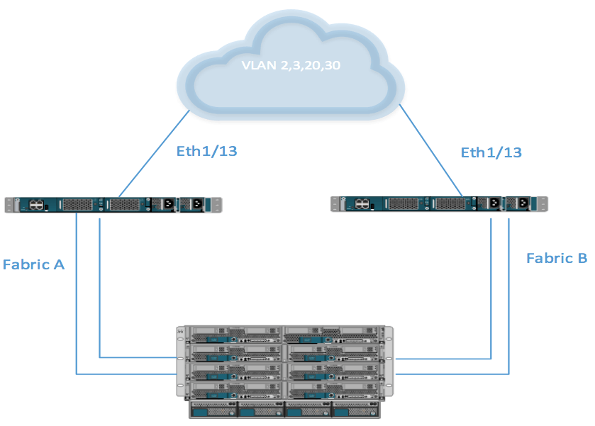
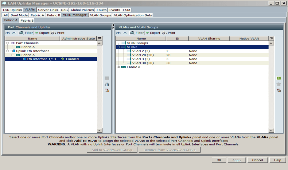
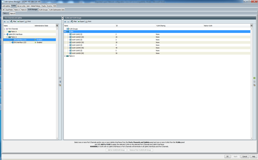
The screenshot below shows the LAN uplink manager configuration, which is the default when you create VLANs and configure Eth1/13 on both FI as uplink port. If you can click on the Fabric B tab, it should appear as shown below:
A disjointed Layer 2 is introduced when you have a physically or logically separated network or networks introduced into the topology.
The diagram below shows the topology of a disjointed Layer 2 network.
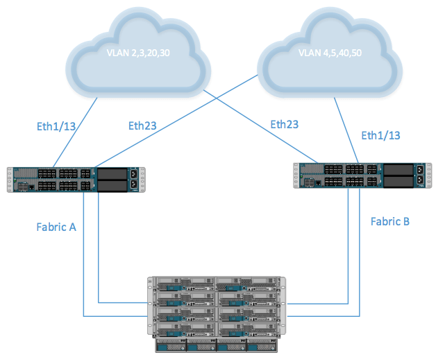
In the diagram above, eth 1/13 on both FIs can’t reach VLANs 4, 5, 40, and 50. Eth1/23 on both FIs can’t reach VLAN 2, 3, 20, and 30.
UCSM 2.0 and above solve this issue by assigning dedicated uplinks to VLANs that they reach. Introducing a disjointed layer changes the default configuration of the uplink switch. You can use LAN uplink manager to add uplink Eth1/23 and VLAN 4, 5, 40 and 50 to the same VLAN/VLAN Group. You can then isolate Eth1/13 and VLAN 2, 3, 20, 30 to their own VLAN/VLAN group.
This accounts for the way UCS operates. Normally, all VLANs are available on all uplinks by default. If you don’t want that, you must define/isolate them to their respective VLAN/VLAN Group. If you do not associate each uplink to its dedicated VLANs some of the blades will have network connectivity problems. If the blade runs as an ESXi host, some VMs will lose network connectivity.
The procedure to properly configure a disjointed Layer 2 is listed below:
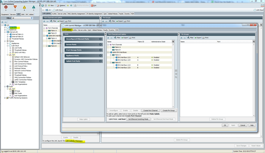
- Login to UCS.
- Click on the LAN tab.
- Click LAN cloud.
- Click on LAN uplink manager.
- Click the VLAN tab.
- Click the VLAN manager subtab.
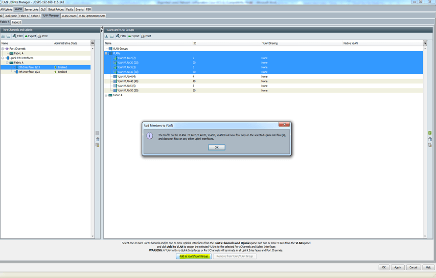
- Click on the uplink (Eth1/13) on the left pane and hold down the Ctrl key and click all the VLANs that will be associated with the uplink on the right pane.
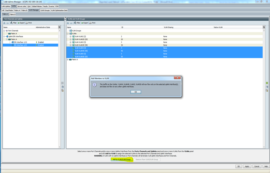
- Next, click on the uplink (Eth1/23) on the left pane and hold down the Ctrl key and click all the VLANs that will be associated with the uplink on the right pane.
- Click Fabric B and repeat steps 6 to 9.
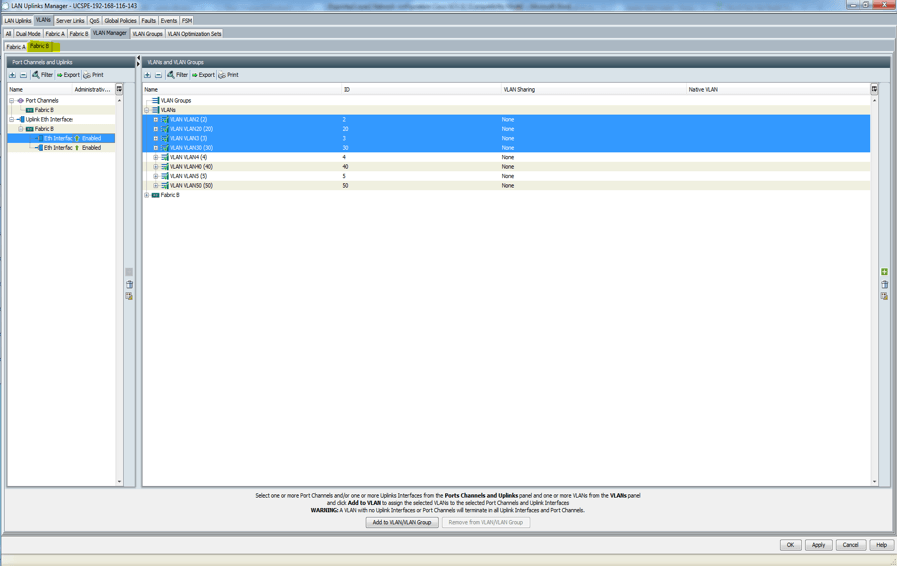
- At the end of the day, it should look like this:
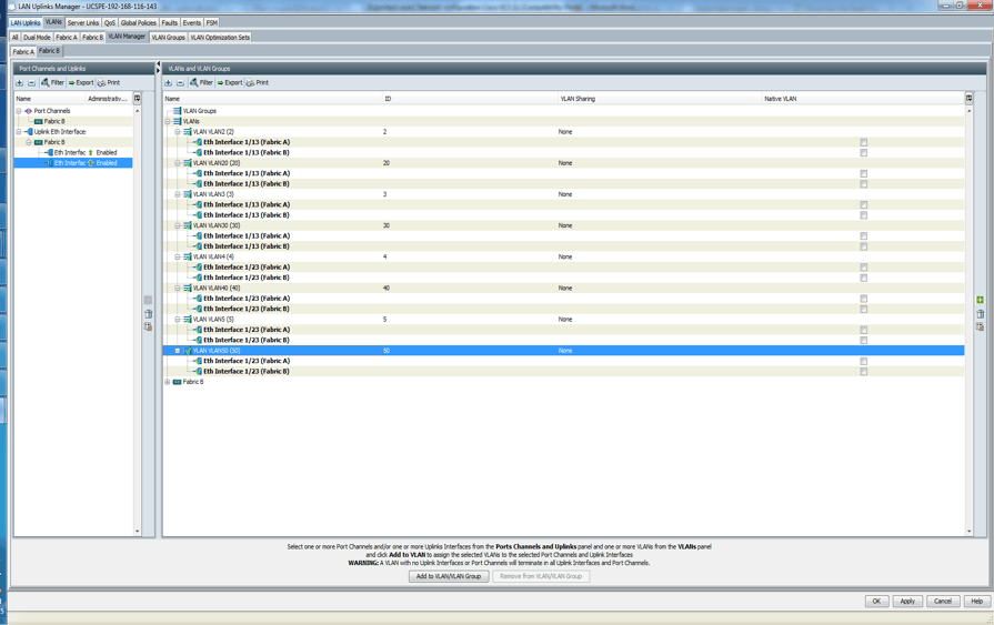
This configuration will ensure that VLANs are associated with the right uplinks. Be careful that any VLAN that is added afterwards is associated with the correct uplink in LAN uplink manager. Remember when you create your vNICs or vNIC template, do not assign VLANs in the two separate network domains to one vNICs. vNICs will only associate with one network domain and not both.