
I’ve recently been looking at BGP designs using route reflectors (RR). As a best practice for RR designs, the logical iBGP sessions should follow the physical topology. But what could happen if you don’t follow this practice?
In a later example, I will allow my RRs to behave badly, and NOT follow the physical topology to see what might happen.
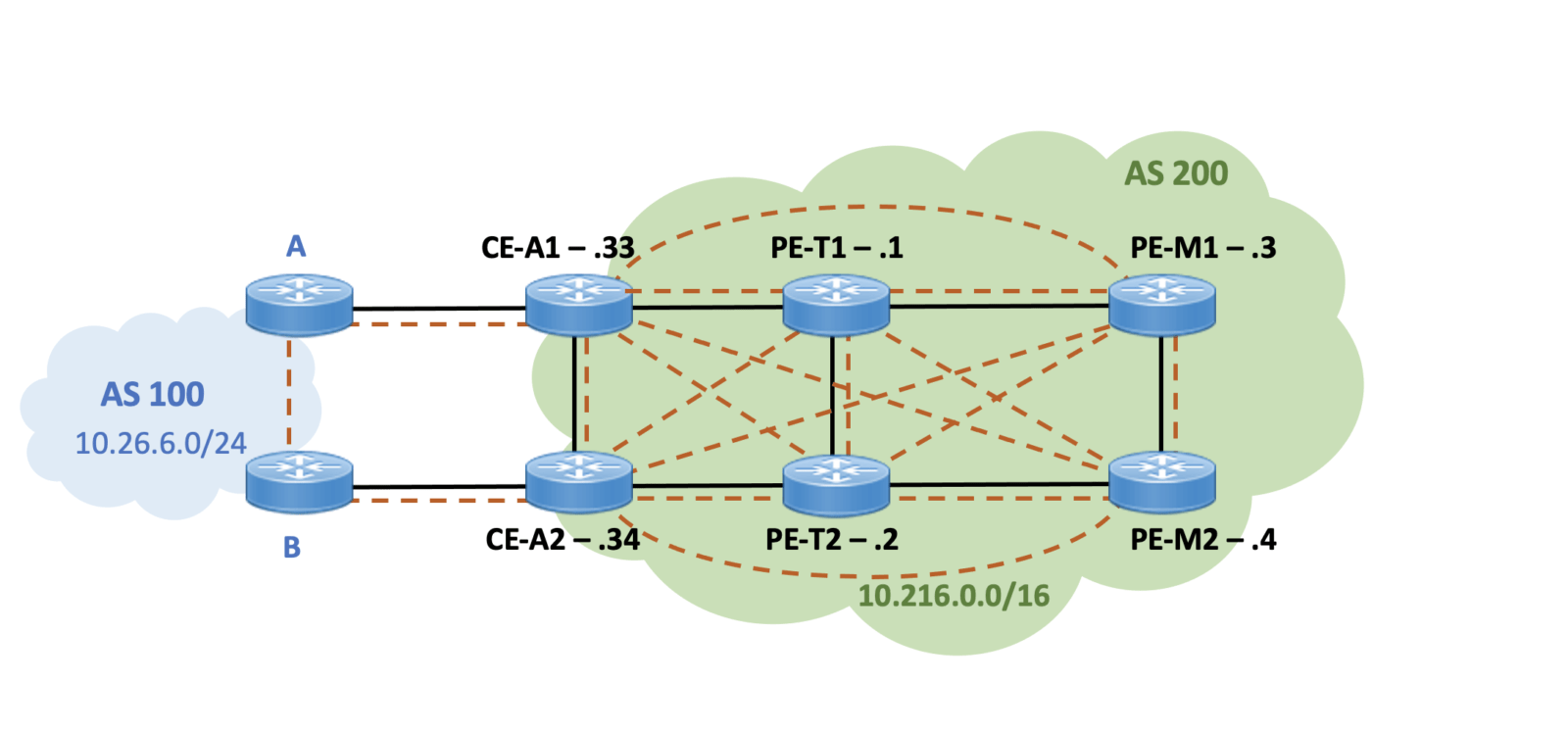
Initially, AS 200 has a full mesh design of iBGP speakers. (I am ignoring how AS 100 is inter-connected.) Routers A and B from AS 100 both send prefix 10.26.6.0/24 to their neighbors. IP address 10.26.6.1 is currently reachable from PE-M1 & PE-M2. The dashed lines show the logical BGP sessions. The thick solid black lines show the physical connectivity in the network.
The basic BGP configuration is straight-forward, all routers in each AS has a full mesh of iBGP sessions to all other BGP speakers in their domain. The two edge routers CE-A1 and CE-A2 have eBGP sessions to edge routers A and B in AS 100.
The following loopback addressing is in place:
- PE-T1 10.216.248.1/32
- PE-T2 10.216.248.2/32
- PE-M1 10.216.248.3/32
- PE-M2 10.216.248.4/32
- CE-A1 10.216.248.33/32
- CE-A2 10.216.248.34/32
All the routers in AS 200 are peering on loopback 0, for example:
!
PE-M2#sh run | beg router bgp
router bgp 200
 no synchronization
 bgp log-neighbor-changes
 neighbor 10.216.248.1 remote-as 200
 neighbor 10.216.248.1 update-source Loopback0
 neighbor 10.216.248.2 remote-as 200
 neighbor 10.216.248.2 update-source Loopback0
 neighbor 10.216.248.3 remote-as 200
 neighbor 10.216.248.3 update-source Loopback0
 neighbor 10.216.248.33 remote-as 200
 neighbor 10.216.248.33 update-source Loopback0
 neighbor 10.216.248.34 remote-as 200
 neighbor 10.216.248.34 update-source Loopback0
 no auto-summary
!
. . .
PE-M2#
Here is what one of the edge router’s BGP configuration looks like:
CE-A1#sh run | beg router bgp
router bgp 200
 no synchronization
 bgp log-neighbor-changes
 neighbor 10.26.6.6 remote-as 100
 neighbor 10.216.248.1 remote-as 200
 neighbor 10.216.248.1 update-source Loopback0
 neighbor 10.216.248.1 next-hop-self
 neighbor 10.216.248.2 remote-as 200
 neighbor 10.216.248.2 update-source Loopback0
 neighbor 10.216.248.2 next-hop-self
 neighbor 10.216.248.3 remote-as 200
 neighbor 10.216.248.3 update-source Loopback0
 neighbor 10.216.248.3 next-hop-self
 neighbor 10.216.248.4 remote-as 200
 neighbor 10.216.248.4 update-source Loopback0
 neighbor 10.216.248.4 next-hop-self
 neighbor 10.216.248.34 remote-as 200
 neighbor 10.216.248.34 update-source Loopback0
 neighbor 10.216.248.34 next-hop-self
 network 10.216.0.0 mask 255.255.0.0
 no auto-summary
!
. . .
CE-A1#
Initially, all devices in AS 200 have two BGP entries to reach 10.26.6.1, for example:
PE-M2#sh ip bgp
BGP table version is 3, local router ID is 10.216.248.4
Status codes: s suppressed, d damped, h history, * valid, > best, i - internal,
              r RIB-failure, S Stale
Origin codes: i - IGP, e - EGP, ? - incomplete

   Network          Next Hop            Metric LocPrf Weight Path
* i10.26.6.0/24     10.216.248.33            0    100      0 100 i
*>i                 10.216.248.34            0    100      0 100 i
*>i10.216.0.0/16    10.216.248.34            0    100      0 i
* i                 10.216.248.33            0    100      0 i
PE-M2#
PE-M2#ping 10.26.6.1

Type escape sequence to abort.
Sending 5, 100-byte ICMP Echos to 10.26.6.1, timeout is 2 seconds:
!!!!!
Success rate is 100 percent (5/5), round-trip min/avg/max = 1/1/4 ms
PE-M2#
Migrating to a BGP Route Reflector Configuration
To test an RR design that does not follow the physical topology, the following physical and logical topology will be implemented:
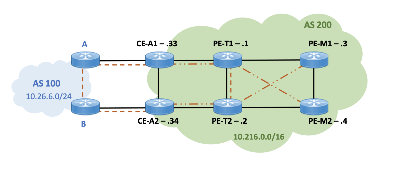
The dashed-dotted lines from PE-T1 and PE-T2 show the logical iBGP sessions to the RR clients. There is also an iBGP session between PE-T1 and PE-T2. The thick solid black lines again show the physical connectivity in the network. (This RR design is NOT a recommended design, but is used here for illustration.)
The following new RR configurations are applied:
!PE-T1
no router bgp 200
router bgp 200
 neighbor 10.216.248.2 remote-as 200
 neighbor 10.216.248.2 update-source lo 0
 neighbor 10.216.248.4 remote-as 200
 neighbor 10.216.248.4 update-source lo 0
 neighbor 10.216.248.4 route-reflector-client
 neighbor 10.216.248.33 remote-as 200
 neighbor 10.216.248.33 update-source lo 0
 neighbor 10.216.248.33 route-reflector-client
!PE-T2
no router bgp 200
router bgp 200
 neighbor 10.216.248.1 remote-as 200
 neighbor 10.216.248.1 update-source lo 0
 neighbor 10.216.248.3 remote-as 200
 neighbor 10.216.248.3 update-source lo 0
 neighbor 10.216.248.3 route-reflector-client
 neighbor 10.216.248.34 remote-as 200
 neighbor 10.216.248.34 update-source lo 0
 neighbor 10.216.248.34 route-reflector-client
! CE-A1
no router bgp 200
router bgp 200
 neighbor 10.216.248.1 remote-as 200
 neighbor 10.216.248.1 update-source lo 0
 neighbor 10.216.248.1 next-hop-self
 neighbor 10.26.6.6 remote-as 100
!CE-A2
no router bgp 200
router bgp 200
 neighbor 10.216.248.2 remote-as 200
 neighbor 10.216.248.2 update-source lo 0
 neighbor 10.216.248.2 next-hop-self
 neighbor 10.26.6.10 remote-as 100
!PE-M1
no router bgp 200
router bgp 200
 neighbor 10.216.248.2 remote-as 200
 neighbor 10.216.248.2 update-source lo 0
! PE-M2
no router bgp 200
router bgp 200
 neighbor 10.216.248.1 remote-as 200
 neighbor 10.216.248.1 update-source lo 0
Verifying the RR Configuration
As expected, the PE-T1 and PE-T2 routers now only have three iBGP sessions, for example:
PE-T1#sh ip bgp sum
BGP router identifier 10.216.248.1, local AS number 200
BGP table version is 2, main routing table version 2
1 network entries using 121 bytes of memory
2 path entries using 104 bytes of memory
2/1 BGP path/bestpath attribute entries using 152 bytes of memory
1 BGP rrinfo entries using 24 bytes of memory
1 BGP AS-PATH entries using 24 bytes of memory
0 BGP route-map cache entries using 0 bytes of memory
0 BGP filter-list cache entries using 0 bytes of memory
BGP using 425 total bytes of memory
BGP activity 1/0 prefixes, 2/0 paths, scan interval 60 secs

Neighbor        V    AS MsgRcvd MsgSent   TblVer  InQ OutQ Up/Down  State/Pfx
10.216.248.2    4   200       6       7        2    0    0 00:04:43        1
10.216.248.4    4   200       5       6        2    0    0 00:02:28        0
10.216.248.33   4   200       5       6        2    0    0 00:03:08        1
PE-T1#
The PE-M1 and PE-M2 routers only have one iBGP session, for example:
PE-M2#sh ip bgp sum
BGP router identifier 10.216.248.4, local AS number 200
BGP table version is 2, main routing table version 2
1 network entries using 121 bytes of memory
1 path entries using 52 bytes of memory
2/1 BGP path/bestpath attribute entries using 152 bytes of memory
1 BGP rrinfo entries using 24 bytes of memory
1 BGP AS-PATH entries using 24 bytes of memory
0 BGP route-map cache entries using 0 bytes of memory
0 BGP filter-list cache entries using 0 bytes of memory
BGP using 373 total bytes of memory
BGP activity 1/0 prefixes, 1/0 paths, scan interval 60 secs

Neighbor        V    AS MsgRcvd MsgSent   TblVer  InQ OutQ Up/Down  State/PfxRcd
10.216.248.1    4   200       5       4        2    0    0 00:02:03        1
PE-M2#
As expected, the RR clients now have one BGP entry towards 10.26.6.1, for example:
PE-M1#sh ip bgp
BGP table version is 3, local router ID is 10.216.248.3
Status codes: s suppressed, d damped, h history, * valid, > best, i - internal,
              r RIB-failure, S Stale
Origin codes: i - IGP, e - EGP, ? - incomplete

   Network          Next Hop            Metric LocPrf Weight Path
*>i10.26.6.0/24     10.216.248.34            0    100      0 100 i
PE-M1#

PE-M2#sh ip bgp
BGP table version is 2, local router ID is 10.216.248.4
Status codes: s suppressed, d damped, h history, * valid, > best, i - internal,
              r RIB-failure, S Stale
Origin codes: i - IGP, e - EGP, ? - incomplete

Network          Next Hop            Metric LocPrf Weight Path
*>i10.26.6.0/24     10.216.248.33            0    100      0 100 i
PE-M2#
Testing Connectivity
So what happens now when PE-M1 or PE-M2 attempts to reach 10.26.6.1?
PE-M1#trace 10.26.6.1

Type escape sequence to abort.
Tracing the route to 10.26.6.1

1 10.216.250.5 0 msec 0 msec 0 msec
2 10.216.250.6 0 msec 0 msec 0 msec
3 10.216.250.5 0 msec 0 msec 0 msec
4 10.216.250.6 0 msec 0 msec 0 msec
5 10.216.250.5 0 msec 0 msec 0 msec
6 10.216.250.6 0 msec 0 msec 0 msec
7 10.216.250.5 0 msec 0 msec 0 msec
8 10.216.250.6 0 msec 0 msec 0 msec
9 10.216.250.5 0 msec 0 msec 0 msec
10 ...
Identifying the Issue
Maybe you saw the issue from the previous show ip bgp results. If not, the routing tables of PE-M1 and PE-M2 help illustrate the problem:
PE-M1#sh ip ro
. . .
Gateway of last resort is not set

      10.0.0.0/8 is variably subnetted, 13 subnets, 3 masks
B        10.26.6.0/24 [200/0] via 10.216.248.34, 00:02:55
D        10.216.248.1/32
           [90/128512] via 10.216.250.9, 00:04:56, TenGigabitEthernet2/0/0
D        10.216.248.2/32
           [90/128768] via 10.216.250.5, 00:04:56, TenGigabitEthernet3/0/0
C        10.216.248.3/32 is directly connected, Loopback0
D        10.216.248.4/32
           [90/128512] via 10.216.250.5, 00:04:56, TenGigabitEthernet3/0/0
D        10.216.248.33/32
           [90/131072] via 10.216.250.9, 00:04:57, TenGigabitEthernet2/0/0
D        10.216.248.34/32
           [90/131328] via 10.216.250.5, 00:04:57, TenGigabitEthernet3/0/0
C        10.216.250.4/30 is directly connected, TenGigabitEthernet3/0/0
L        10.216.250.6/32 is directly connected, TenGigabitEthernet3/0/0
C        10.216.250.8/30 is directly connected, TenGigabitEthernet2/0/0
L        10.216.250.10/32 is directly connected, TenGigabitEthernet2/0/0
D        10.216.250.128/30
           [90/3072] via 10.216.250.9, 00:04:57, TenGigabitEthernet2/0/0
D        10.216.250.132/30
           [90/3328] via 10.216.250.5, 00:04:57, TenGigabitEthernet3/0/0
PE-M1#


PE-M2#sh ip ro
. . .
Gateway of last resort is not set

      10.0.0.0/8 is variably subnetted, 13 subnets, 3 masks
B        10.26.6.0/24 [200/0] via 10.216.248.33, 00:03:03
D        10.216.248.1/32
           [90/128768] via 10.216.250.6, 00:04:37, TenGigabitEthernet3/0/0
D        10.216.248.2/32
           [90/128512] via 10.216.250.13, 00:04:37, TenGigabitEthernet2/0/0
D        10.216.248.3/32
           [90/128512] via 10.216.250.6, 00:04:37, TenGigabitEthernet3/0/0
C        10.216.248.4/32 is directly connected, Loopback0
D        10.216.248.33/32
           [90/131328] via 10.216.250.6, 00:04:38, TenGigabitEthernet3/0/0
D        10.216.248.34/32
           [90/131072] via 10.216.250.13, 00:04:38, TenGigabitEthernet2/0/0
C        10.216.250.4/30 is directly connected, TenGigabitEthernet3/0/0
L        10.216.250.5/32 is directly connected, TenGigabitEthernet3/0/0
C        10.216.250.12/30 is directly connected, TenGigabitEthernet2/0/0
L        10.216.250.14/32 is directly connected, TenGigabitEthernet2/0/0
D        10.216.250.128/30
           [90/3328] via 10.216.250.6, 00:04:38, TenGigabitEthernet3/0/0
D        10.216.250.132/30
           [90/3072] via 10.216.250.13, 00:04:38, TenGigabitEthernet2/0/0
PE-M2#
The network has a routing loop. When PE-M1 tries to forward traffic to the BGP-learned 10.26.6.0 addresses, it looks up the IGP address of the next hop to CE-A2 (address 10.216.248.34). The IGP next hop to 10.216.248.34 is PE-M2 at 10.216.250.6. So PE-M1 forwards the traffic to PE-M2.
When PE-M2 tries to forward traffic to the BGP-learned 10.26.6.0 addresses, it looks up the IGP address of the next hop to CE-A1 (address 10.216.248.33). The IGP next hop to 10.216.248.33 is PE-M1 at 10.216.250.6. So PE-M2 forwards the traffic back to PE-M1.
Net result: PE-M1 and PE-M2 have formed a routing loop, and will continue to loop the traffic for 10.26.6.0/24.
Summary
In BGP designs with route reflectors, the logical iBGP sessions really should follow the physical topology. This practice helps prevent routing loops.
To resolve the routing loop in this example, CE-A1 and PE-M1 should be RR clients of only PE-T1, and CE-A2 and PE-M2 should be RR clients of only PE-T2. With this updated design, the logical and the physical topology would match, and the routing loop avoided.
— cwr
Hi carole,
Great post…